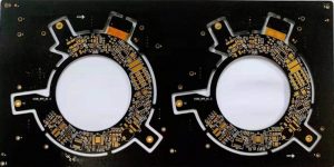
Considerations for Flex PCB Fabrication
The design phase of any PCB is crucial to ensure that the final product satisfies your specifications. But for flex circuits, additional considerations must be taken into account to ensure that the end-product can withstand repeated bending.
These considerations include the type of materials used, the thickness of the layers and the layout of the traces. Understanding how these factors affect the final flex circuit fabrication will help you make an informed decision about whether this is a suitable solution for your project.
Flex circuits are a unique PCB technology that allows them to be used in a wide range of applications. They are thin and lightweight, making them easy to crease and fold. They are also very flexible, allowing them to be positioned in areas where other circuits cannot fit. In order to maximize the flexibility of a flex circuit, it is important to plan the layout of your conductor traces carefully. This includes choosing the appropriate copper plating and etching process.
One key consideration when planning the layout of a flex circuit is the minimum bend radius. This is the smallest angle that the flex circuit can bend without damaging the copper. This value should be determined early in the design process, so that it can be incorporated into the CAD model of your circuit. It is also important to minimize the use of vias in a flex circuit, as they can add extra weight and complexity to the design. If you must use them, it is best to use blind or buried vias.

Design Considerations for Flex PCB Fabrication
When routing traces near the bend areas of the circuit, it is important to avoid sharp edges. Instead, choose rounded edges that are more resistant to stress. This will help prevent the traces from tearing during flexing and improve the reliability of the circuit. In addition, it is recommended to stagger the width and spacing of the traces to reduce the amount of pressure applied to each area during bending.
Other important considerations when designing a flex circuit are the type of materials to be used and the operating environment. For example, adhesive-based flex circuits are more likely to absorb environmental moisture and may be less durable than epoxy-based flex circuits. In addition, flex circuits with exposed copper surfaces are susceptible to corrosion and must be treated with special chemicals to maintain their durability.
The flex pcb fabrication process involves several steps, including the formation of a metal layer and the application of solder to bond it to the conductors. For high-volume production, the flex circuit is cut out using a hydraulic punch and die set, which involves relatively high tooling costs. However, for prototypes and low-volume production, a blanking knife is typically used to cut the flex circuit. This technique is a more cost-effective option and allows the flex circuit to be cut from both sides of the board. It also helps to avoid the need for rework due to faulty cuts or misplaced components.
